PDF-R FlexRay Electrical Timing Analysis Datasheet
FlexRay Electrical Validation and Protocol Decode Software offers electrical measurements compliance testing and protocol decoding as specified in FlexRay specification. PDF-R FlexRay Electrical validation and Protocol decode software runs in Tektronix Oscilloscope provides electrical measurements and protocol decode at click of button. This allows engineers quickly check for FlexRay compliance and flexibility to debug the failure. In addition to this engineer can decode the command and response of FlexRay debug the communication. PDF-R FlexRay takes advantage of digital channels of MSO and provides the decoding of FlexRay data lines.

PDF-R FlexRay Protocol decode and Signal Integrity software offers industry best solution for debugging and testing FlexRay signals using high performance windows based Tektronix oscilloscopes DPO5000/7000/70000.
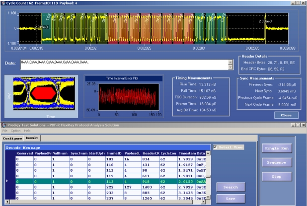
This software enables the designer to capture thousands of FlexRay messages and display the decoded data. PDF-R FlexRay decode feature allows the users to view the decoded data in hex format and decimal format as configured by user. Overlapping the decoded data on waveform viewing it simultaneously on waveform would enable to locate the inaccurate signal transitions.
Signal Integrity
Electronics should work in extreme operating conditions in an automobile. To ensure this performance, FlexRay signals at physical layer should have enough design margins.
PDF-R Software’s signal Integrity features quickly helps in analyzing electrical characteristics of FlexRay signal. The advanced features Eye diagram analysis, time interval error, and sync measurements in PDF-R software enables user to know the eye opening, jitter, and synchronization sequence in a FlexRay network.
Advanced Debug Capabilities
The powerful PDF-R software enables the designer to locate the cause of the problem using advanced analysis capabilities. The software based trigger features enable user to focus on desired information FlexRay to locate a problem. The distinguished view of eyediagram for selected frame and for the entire data helps in locating problem to a node. Simultaneous view of decoded data with waveform with color distinction helps to locate protocol decodes problems due to problem electrical characteristic of signals.
Features
- Converts time domain waveform information into data domain and displays the contents in FlexRay message format
- Simultaneous waveform and decoded data display in single window allows efficient debugging
- Ability to link any FlexRay frame or any message (data or address) to waveform allows efficient analysis of FlexRay communication
- PDI waveform window plots the waveform and display ‘1’ and ‘0’ annotation in zoomed waveform window
- Search function helps in quickly locating the specific data or address in thousands of decoded FlexRay messages
- Time stamp with reference to trigger position allows users know the timing from the trigger position
- Software based trigger features enables user to view the decoded data
- Software trigger features enable the user to set trigger on content of the FlexRay frame, Null frame or a sync frame, CRC error
- Offline analysis with the Ref waveforms, .wfm (Tektronix Oscilloscope’s internal waveform file format) and csv files
- Capability to save the decoded messages in CSV format
- Ability to view the eye diagram for slected message with the complete acquired data helps in pinpointing the cause
- Time interval error analysis for each frames helps in understanding influence of oscillator stability in each FlexRay node
- Sync measurements enables user to know time laps between the sync frames
- Average bit time measurement
